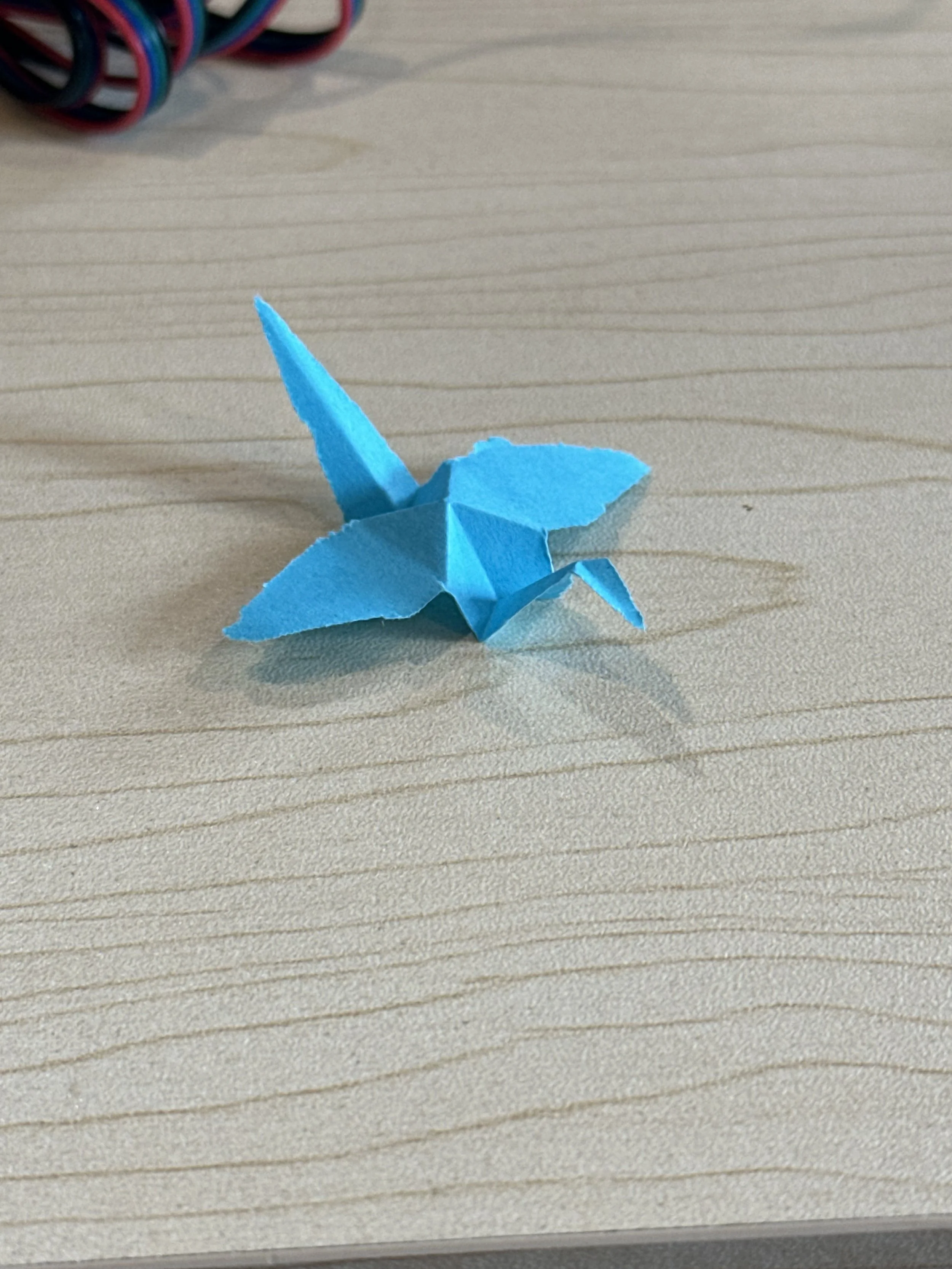
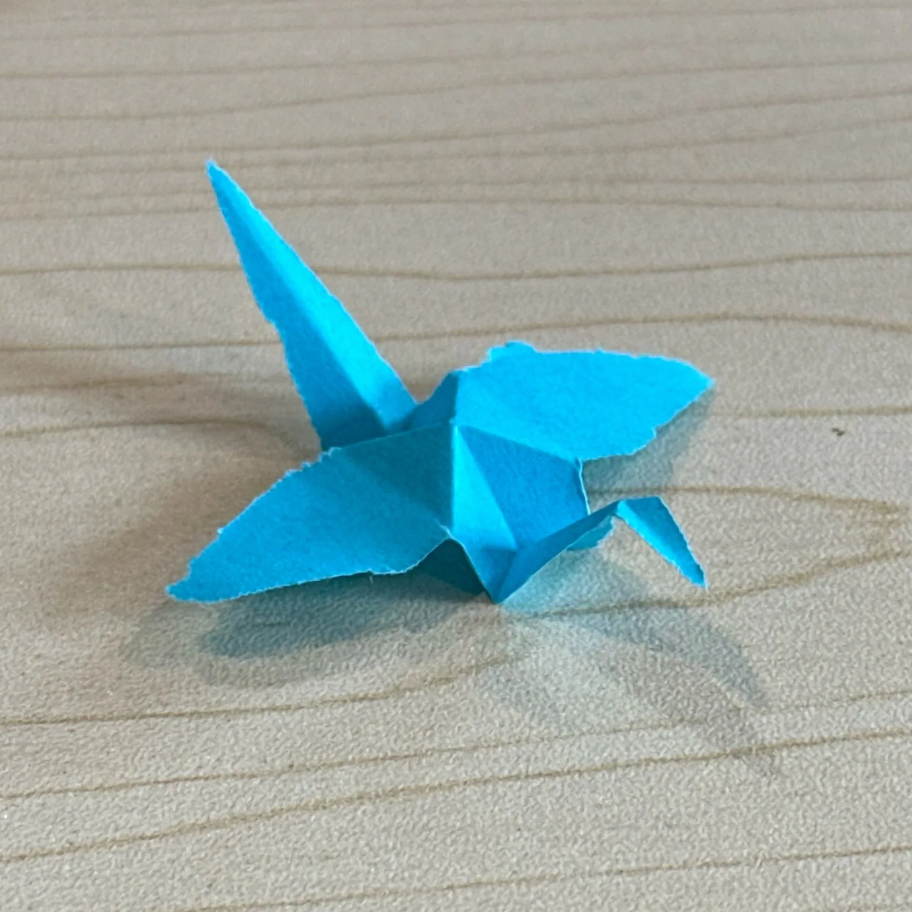
A machine to automatically make paper cranes
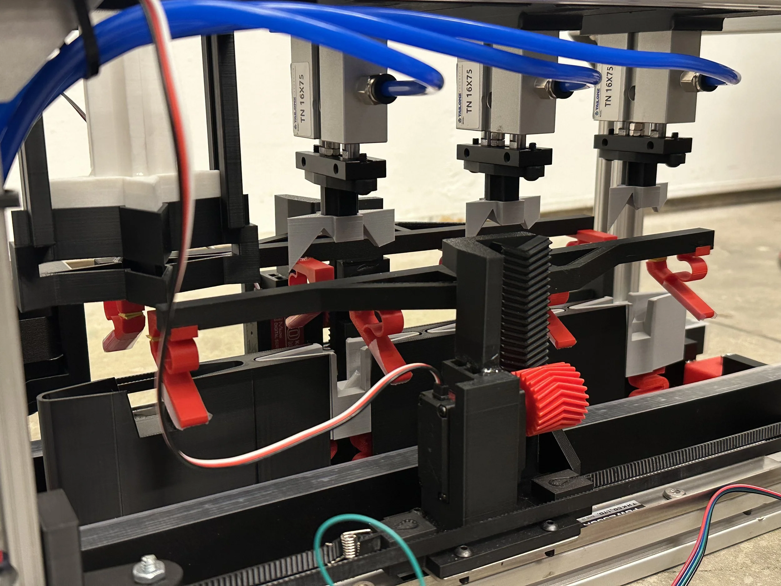
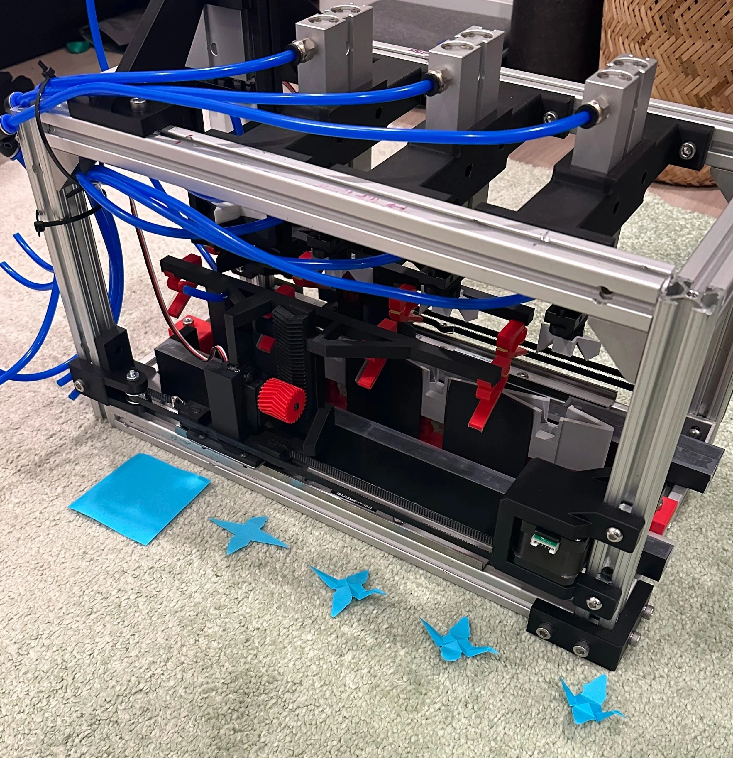
The assembly line has 4 operations:
The first cuts a post-it-note into the right shape, and the other 3 progressively fold the crane sharper and sharper
Here it is an action:
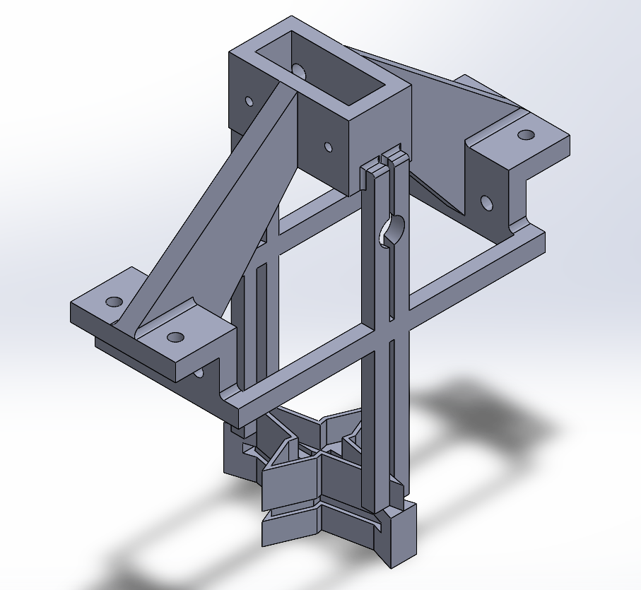
The pnuematic cylinder punches down to fold the paper, and the transfer arm moves it to the next station.
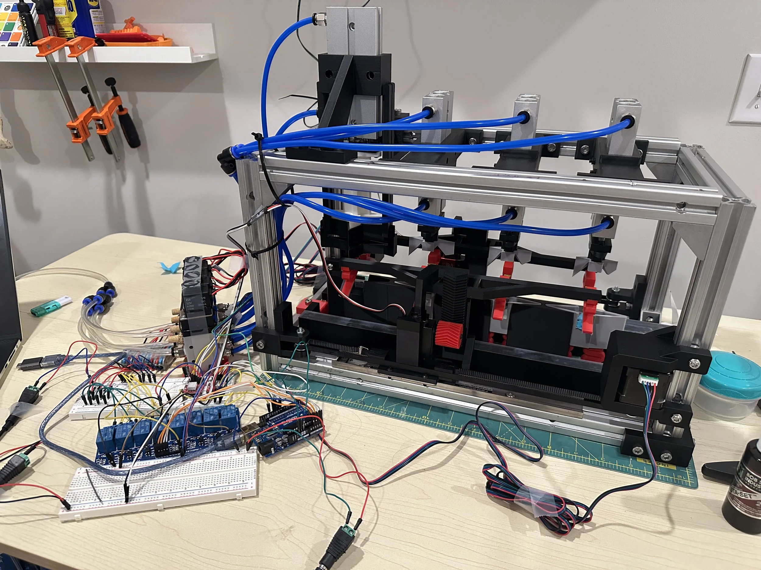
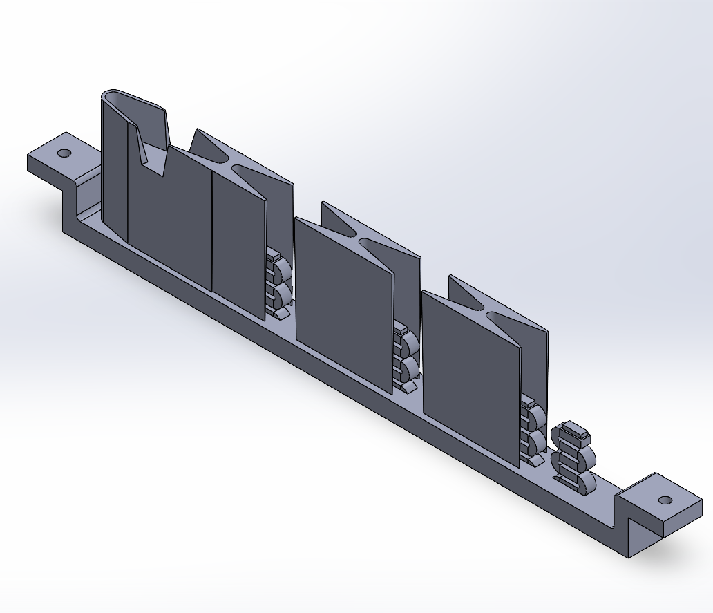
At the end of the video, you might’ve noticed the clips missing the paper. It’s a problem I’m having with every step besides the one you just saw above. Here it is, failing at the start.
Here’s a video showing how the clips grab the paper.
Notice that the clips on either side aren’t exactly level with one another- this causes the paper to get grabbed by one side and missed by the other, resulting in the failures. I’ve detailed some potential fixes at the bottom of the page.
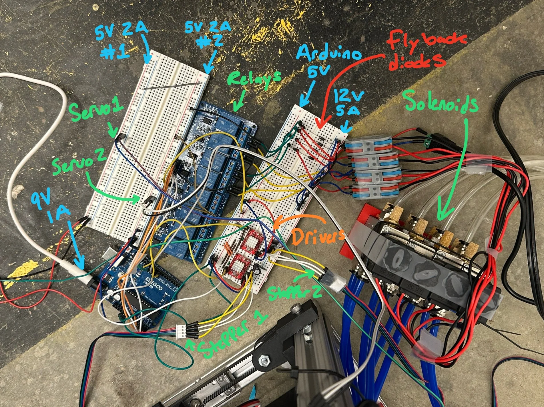
In circuit:
12V-5A supplies stepper drivers and solenoids. Decoupling capacitors and flyback diodes are added respectively.
Seperate 5V-2A supplies power the servos. Relay board borrows ~300 mA from one.
9V-1A powers arduino, arduino 5V connects to drivers and relay board components.

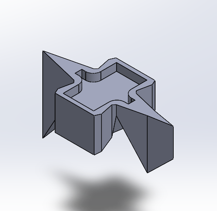
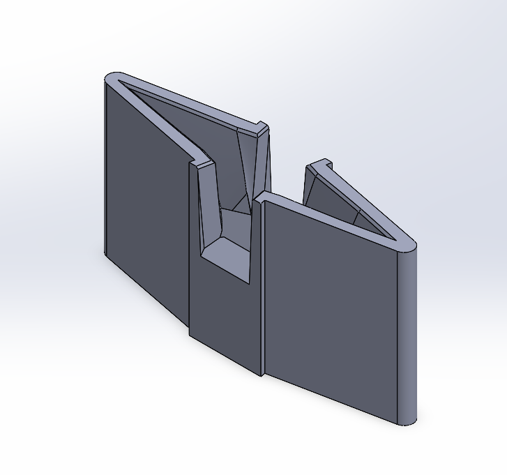
Folding the crane
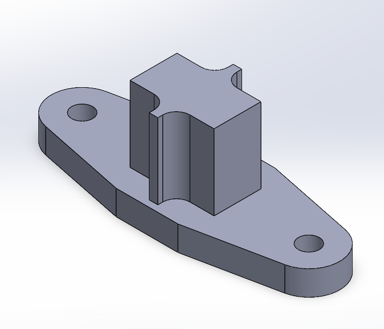
I decided going from a square sheet to an origami crane was too complex, so I redesigned the crane into a shape that can be folded with just one press between two interlocking pieces.
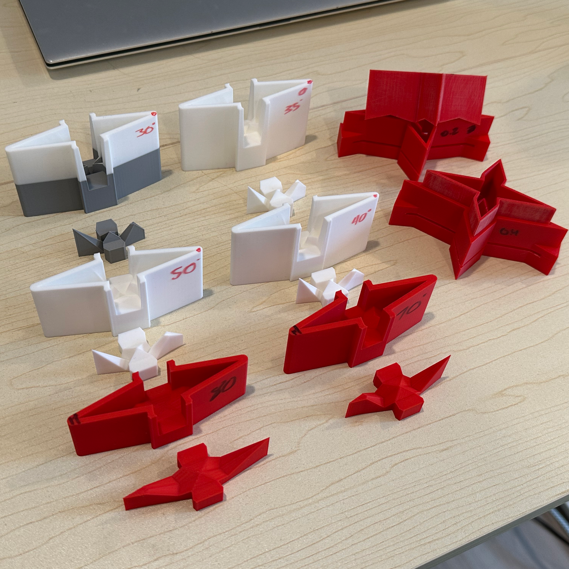
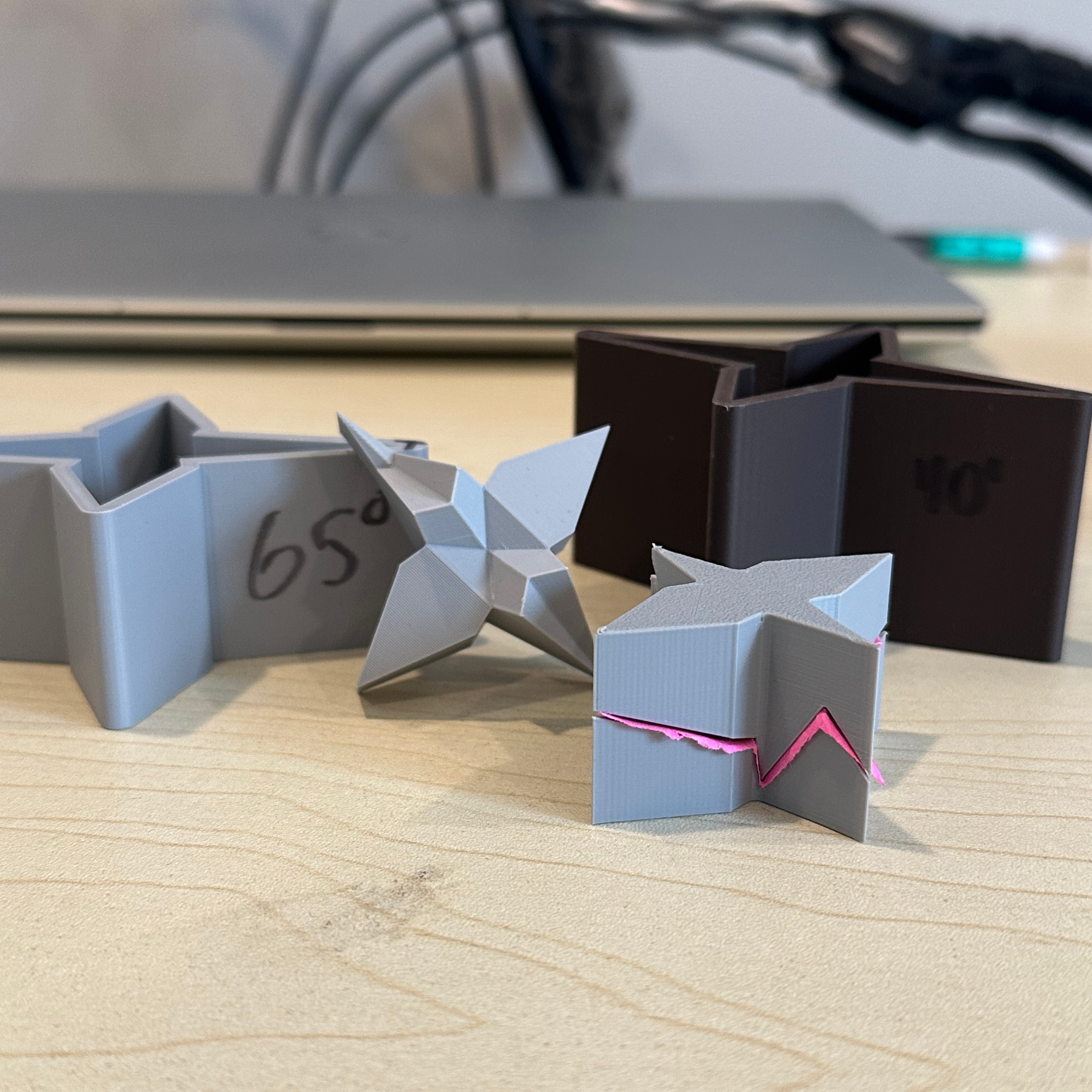
Unfortunetely, the paper rips if you try to go from flat to fully folded, so I needed an easy way to test which degrees of folding could fold the crane in the least number of stages
The parametric model below helped with that, and some of the testing I did can be seen on the far right
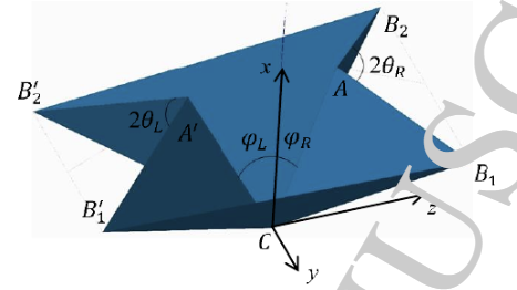
Parametric Folding Crane Model
Math and downloads
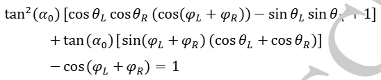
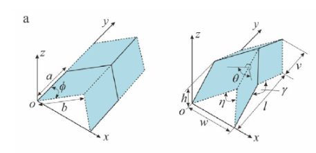
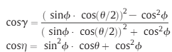
The crane is built with the two patterns below (waterbomb and miura-ori) and they interface in a such a way where they can be modelled pretty much exclusively with the topmost equation to the right of the images. To change how folded the crane is, just change theta.
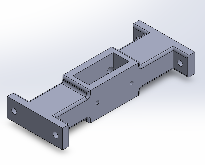
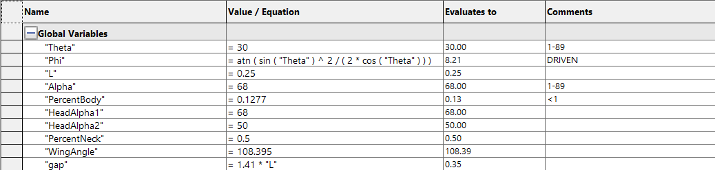
I also added the ability to change the angle or length of the tail, neck, or head, represented by the alpha and percent values in the variable chart to the right. The base file is linked to the right. I’ve also added the final brace to show how the base file was used in it.
Base Crane.SLDPRT
Any parameter set as a value can be changed. For the percents, start with small changes. Alphas can be from 1°-89°.
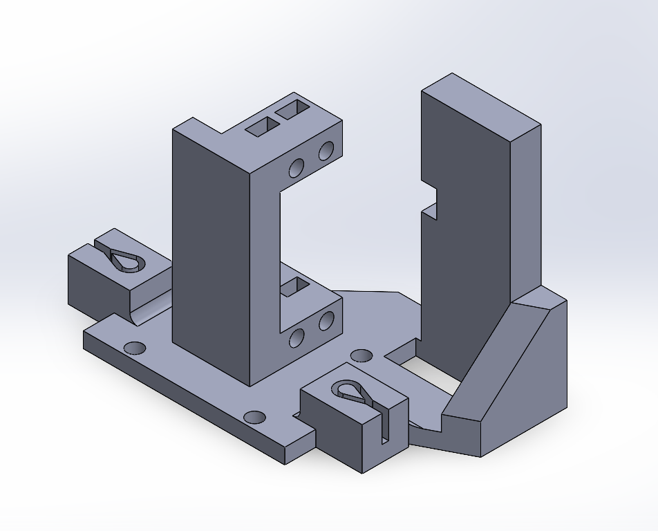
Final Crane Press.SLDPRT
Solidworks is pretty resistant to changes with this one. Theres a chamfer and move face you’ll probably have to delete before changes populate, and if you want to go lower than 30° on theta you’ll have to increase the distance on the 3 visible planes.
In the far future, I imagine the tool being a handheld punch that you could hold over a piece of paper and instantly make a crane. At the moment though, I’ve highlighted some problems for the next prototype.
Making the cutout shape a little smaller so there’s more clearance between the die walls and the jagged paper edge
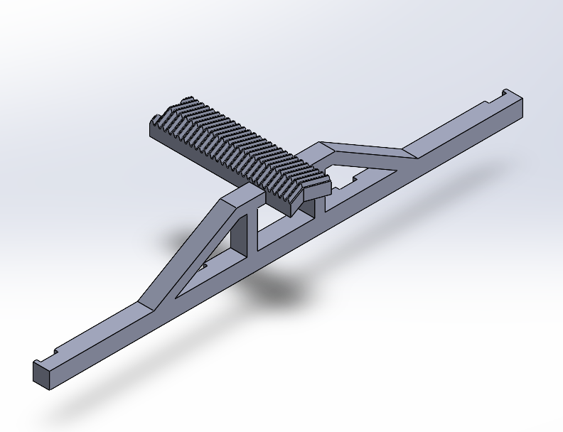
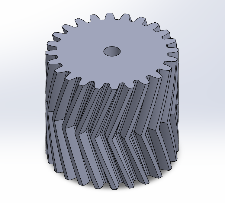
Decrease the tolerance between the gear and rack so the clips line up
Add a metal topper to the long thin arm holding all the clips
Resetting servos to 0 before putting the gear on and orienting it’s topmost tooth perfectly vertical